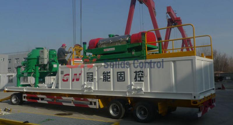
Decanter Centrifuge Intro as well as Software

JQB6545 Decanter Centrifuge was created through GN Solids Manage for that customers in order to configure as well as procedure the actual drilling dirt rapidly within the essential oil & gasoline nicely drilling, HARD DISK DRIVE along with other industrials.

We want drilling liquid (mud) along the way associated with drilling the essential oil nicely in order to awesome the actual rig mind, lubricate the actual rig so the drilling might be simple, as well as provide the actual drilling cuttings from the nicely. Therefore, the actual drilling fuids performs a vital part within the essential oil drilling. In order to configure the actual drilling dirt rapidly brings a lot benifit for that customers. It’s without doubt how the Decanter Centrifuge may be the the majority of valued gear to supply the quickly constitute as well as remedy associated with dirt.

The actual distribution as well as hydrolyze associated with bentonite contaminants within drinking water tend to be managed through: content material associated with electrolyte within drinking water, period, heat, quantity as well as situation, Decanter Centrifuge may certainly boost the hydrolyzing level of bentonite contaminants. The actual molecular pounds associated with higher molecular substance within dirt is actually big and never simple to end up being hydrolyzed straight as well as have to be sheared through Decanter Centrifuge.If in doubt, please contact us.

How to set up decanter centrifuge speed for VFD and PLC system

Functions of decanter centrifuge speed for VFD and PLC system

Normal
0

7.8 磅
0
2

false
false
false

EN-US
ZH-CN
X-NONE

/* Style Definitions */
table.MsoNormalTable
{mso-style-name:普通表格;
mso-tstyle-rowband-size:0;
mso-tstyle-colband-size:0;
mso-style-noshow:yes;
mso-style-priority:99;
mso-style-qformat:yes;
mso-style-parent:””;
mso-padding-alt:0cm 5.4pt 0cm 5.4pt;
mso-para-margin:0cm;
mso-para-margin-bottom:.0001pt;
mso-pagination:widow-orphan;
font-size:10.5pt;
mso-bidi-font-size:11.0pt;
font-family:”Calibri”,”sans-serif”;
mso-ascii-font-family:Calibri;
mso-ascii-theme-font:minor-latin;
mso-hansi-font-family:Calibri;
mso-hansi-theme-font:minor-latin;
mso-font-kerning:1.0pt;}

Decanter centrifuge is widely used for drilling rig mud system; it can be used from barite recovery, fine solids separation, as well as for waste management. It is utilizing different speed to vary G force and to separate different size solid particles from drilling fluids. In this case, centrifuge G force is very important for the performance.  

How to change decanter centrifuge speed for VFD and PLC system

It is actually differential speed what decides G force. Differential speed have relationship with bowl speed, gearbox input speed and the gearbox ration. Gearbox ration is usually a fixed figure for a certain decanter centrifuge model. Below is the relationship of them:

Differential Speed = ( Bowl speed – Gearbox input speed) / Gear Box Ration

 Take GNLW363VFD decanter centrifuge as an example, Gear Box Ration=57. Blow speed and gearbox input speed (conveyor speed) is changeable; they can be set on the PLC touch screen of the VFD centrifuge.  

decater

So Gearbox input speed=Bowl Speed – 57×Differential Speed= Small Motor Speed transferred to gearbox by belt, in some occasions, it is also called conveyor speed.

 Below we see 2 examples

Case 1) Bowl speed=3200RPM, and Differential Speed=30RPM

Gearbox Input speed=3200-57×30=1490RPM ,

Case 2) Bowl speed=1200 RPM, differential speed=35 RPM

Gearbox Input Speed= 1200-57×35= -795RPM it is a negative number.

Above situation, you can see, sometimes the gear box speed is  a positive number, that means small motor running according to the Arrow on the belt cover. Watching from feeding tube side the small motor rotation is Anticlockwise.

The motor speed is changed for some condition. GN brand VFD centrifuge have program to control the motor speed and motor direction. It can changed automatically when necessary.


Save Money by Buying mud Cleaner and cuttings dryer

 Check whether the indications on the nameplates of the motors and the Mud Cleaner are in accordance with the ordering information or operational cuttings dryer. B. Dismantle the wedges under the gearbox and main pulley at both sides of the unit assembly of revolving part respectively,
   Installation of centrifuge There are two alternative installation modes: firstly, ride between the two mud tanks where spacing is reserved, the reserved space between the two tanks can be utilized to discharge solids. secondly, put on the upper part of mud tanks. The groove slide carriage corresponding to the dirt excluding groove is provided by the customer, which guides solid materials to the grit chamber along the slide carriage.

The clarified effluent outlet is connected to the tank with flexible pipe. Sufficient space for operation and maintenance around the centrifuge and a space of not less than 1100mm long at the side of slurry inlet shall be remained, so as to pull out feed tube. 1.3 Installation of feed pump and pipeline connectionTwo types of feed pump with different service theory are available for either rated frequency or frequency conversion centrifugal machine.

mud system introduce from gn company

Operation principle of differential’s safety device Safety device is mounted at the left of the differential so as to make sure no damage occur when overload(See Figure 5). It is a ball clutch, it mainly composed of drive plate, jaw, cam, ball and dish spring. Under the force of dish spring, cam is pressed tightly on the ball of drive plate. then transmit auxiliary motor’s torque to differential’s input shaft, when exceed set torque, drive plate will break away from ball and slip along the cam surface, jaw of the clutch will break off, auxiliary motor rotate with no-load , at the same time, drive plate move axially to make limit switch act under the force of spring, cut off the power of main motor, auxiliary motor, mud filling pump simultaneously. When this kind of problem occur, check carefully if it is caused by of overload, then reset clutch at working condition after solving the problem. The method is: remove the nuts to loose the cam; put the ball’s slot onto the ball of cam , tighten the nut to inlay 2.5mm into jaw, mount limit switch well to keep push rod 1mm away from clutch drive plate. 3.2.5Operation Principle of hydraulic coupler Hydraulic coupler is mounted on main motor, it is a mud system, it have the function of buffering starting shock, reduce starting current and overload protection. Its structure is in Figure 6, it consists of shell, turbine, pump wheel, input shaft, output pulley; shell is joined with turbine, output pulley connect with shell; input shaft connect with pump wheel, working oil is filled into the shell, pressure emerges in service oil caused by centrifugal force when motor axle drive turbine to rotate, in this way, power is transmitted. Motor’s no-load starting can achieve when motor start-up in lower speed because less liquid pressure and smaller drag exist at this time when reaching its rated rotational speed, oil pressure increase and drive load to rotate, this is coupler’s buffering starting shock principle; When load is too heavy, speed differential between pump wheel and turbine increase , oil is heated immediately, meltable plug in the coupler will be melted when oil temperature exceed 120°c, oil sprays out to make input separate from output, thus main motor is protected and make sure no burn occurs, oil is the media of transmission, so its performance will influence coupler’s working condition. Replace the oil as required(Refer to item 5.3 mud system for sale for further information),know more solids control pls click here to visit.

attention Before operating solids equipment

Before operating, must check the bolts to confirm whether there is loose or not. Otherwise, we must screw bolts tight before running shaker Inspect the cable, whether there is wear, hold down, crushing, etc. the vibration motor should be under good lubrication during operation: Motors before fixed on shaker, the bearing is filled with SKF specific lubricate grease, the temperature range is -40 ~ 200℃ During running, every 2000 working hours user should makeup LGHP2 lubricate grease once. Every bearing can not be filled over 25.8g During 2000 hours, if any bearing daily temperature increase (temperature increase means motor shell actual one deduct environment temperature, every half one month test on bearing temperature increase is requested) 10° than common situation. This means the lubrication isn’t sufficient. At this time, the lubrication schedule and lubrication grease make up quantity should be decreased properly. In principle, every 2000hours, every bearing lubrication grease makeup should be less than 25.8g. Such as, lubrication period will be deducted half of usual quantity (1000 hours) while lubrication grease make up should be less than 12.9g. Usually, bearing daily temperature increase every 10°, lubrication period and make up quantity should be decreased once. To make sure solids control equipmentoperated well, we must use LGHP2 grade high temperature lubrication grease. Before adding new lubrication grease we should clean the input hole. Commonly, bearing will have natural temperature increase by 1-2℃ just after lubricating or second lubrication, A world-renowned platform is also introduced in this regard, please refer to Solids Control introduce. To avoid dust fall into oil input hole, or wear bearing, usually we’ll use oil cup to close oil hole If we operate the shale shaker after long time off status, we need to inspect motor rotary unit on insulation. Use 500V Ω gauge, get resistance is not larger than 0.5MSZ, we can run the shaker. Notice: ① If the motor doesn’t run at all, we must shut off the power immediately to avoid motor broken ② After starting motor, to inspect, whether this is any problem. If there is any break off or uncommon noise. If two motors are not running in-phase we need to stop the motors and get rid of problems then turn it on again for operation ③ When motor is under cold status, should not be started 5 times continuously; when motor is turned off under hot status, the restart can not be over 3 times continuously,at the same time,pls click itto know more.